>> P.527
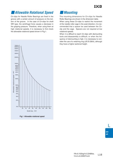
LL18■Allowable Rotational Speed■MountingCir-clips for Needle Roller Bearings are fixed in the The mounting dimensions for Cir-clips for Needle groove with a certain amount of pressure on the bot-Roller Bearings are shown in the dimension table. tom of the groove. In the case of Cir-clips for shaft When using these Cir-clips to restrict the movement WR type, the centrifugal force causes a decrease in of the needle roller cage in the axial direction, it is rec-the gripping pressure. Therefore, when using them at ommended that a spacer be used between the Cir-high rotational speeds, it is necessary to rst check clip and the cage. Spacers are not required at low the allowable rotational speed shown in Fig.1. rotational speeds. When it is difficult to reach Cir-clips with dismounting tools and disassembly is difficult, or when the fre-quency of dismounting is high, it is necessary to con-sider the use of a retaining ring (JIS B 2804), although they have a higher sectional height.20406080100120140160180Shaft dia.mmFig.1 Allowable rotational speed7000060000500004000030000200001000080007000600050004000300020001000800700600500400300200100min-1Allowable rotational speed
 | <
| <  |
|  > |
> |  >>
>>