>> P.137
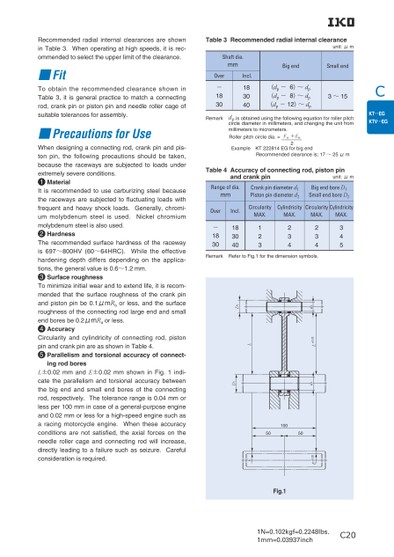
C1N=0.102kgf=0.2248lbs.1mm=0.03937inchTable3Recommendedradialinternalclearanceunit:μmBigendSmallend(dp- 6)〜 dp(dp- 8)〜 dp(dp-12)〜 dp3〜15Shaftdia.mmOverIncl.183040-1830Remark pisobtainedusingthefollowingequationforrollerpitchcirclediameterinmillimeters,andchangingtheunitfrommillimeterstomicrometers.Rollerpitchcircledia.=Fw+Ew ExampleKT222814EGforbigend Recommendedclearanceis;17〜25μm2Table4Accuracyofconnectingrod,pistonpinandcrankpinunit:μmRangeofdia.mmCrankpindiameterd1Pistonpindiameterd2BigendboreD1SmallendboreD2OverIncl.CircularityCylindricityCircularityCylindricityMAX.MAX.MAX.MAX.345234234123183040-1830Remark RefertoFig.1forthedimensionsymbols. C202d±0.02L1dLD2D11005050±0.02EEFig.1RecommendedradialinternalclearancesareshowninTable3.Whenoperatingathighspeeds,itisrec-ommendedtoselecttheupperlimitoftheclearance.■FittherecommendedclearanceshowninToobtainTable3,itisgeneralpracticetomatchaconnectingrod,crankpinorpistonpinandneedlerollercageofsuitabletolerancesforassembly.■PrecautionsforUsetothattofluctuatingisrecommendedfollowingprecautionsshouldbethetheracewaysaresubjectedWhendesigningaconnectingrod,crankpinandpis-tonpin,taken,loadsunderbecauseextremelysevereconditions.1MaterialtousecarburizingsteelbecauseIttheracewaysaresubjectedloadswithfrequentandheavyshockloads.Generally,chromi-ummolybdenumsteelNickelchromiummolybdenumsteelisalsoused.2HardnessTherecommendedsurfacehardnessofis697〜800HV(60〜64HRC).Whilehardeningdepthdiffersdependingontions,thegeneralvalueis0.6〜1.2mm.3SurfaceroughnessTominimizeinitialwearandtoextendlife,itisrecom-mendedthecrankpintheracewaytheeffectivetheapplica-thesurfaceroughnessofisused.andpistonpinbe0.1μmRaorless,andthesurfaceroughnessoftheconnectingrodlargeendandsmallendboresbe0.2μmRaorless.4AccuracyCircularityandcylindricityofconnectingrod,pistonpinandcrankpinareasshowninTable4.5Parallelismandtorsionalaccuracyofconnect-ingrodboresinFig.1theparallelismandL±0.02mmandE±0.02mmshownindi-torsionalaccuracybetweencatethebigendandsmallendboresoftheconnectingrod,respectively.Thetolerancerangeis0.04mmorlessper100mmincaseofageneral-purposeengineand0.02mmorlessforahigh-speedenginesuchastheseaccuracyaracingmotorcycleengine.conditionsarenotsatisfied,theneedlerollercageandconnectingrodwillincrease,directlyleadingtoafailuresuchasseizure.Carefulconsiderationisrequired.Whentheaxialforceson
 | <
| <  |
|  > |
> |  >>
>>