>> P.121
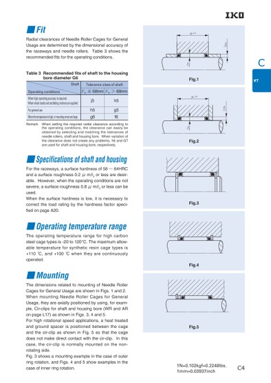
C1N=0.102kgf=0.2248lbs.1mm=0.03937inchDw|32Dw2|3C4BcH11Fig.1H11BcDwFig.2DwFig.3Fig.4Fig.5■FitRadial clearances of Needle Roller Cages for General Usage are determined by the dimensional accuracy of the raceways and needle rollers. Table 3 shows the recommended ts for the operating conditions.Table 3 ecommended fits of shaft to the housing bore diameter G6ShaftTolerance class of shaftOperating conditionsFw≦68mmFw>68mmWhen high operating accuracy is required. When shock loads and oscillating motions are applied.For general useWhen the temperature is high, or mounting errors are large.j5h5g6h5g5f6Remark When setting the required radial clearance according to the operating conditions, the clearance can easily be obtained by selecting and matching the tolerances of needle rollers, shaft and housing bore. When variation of the clearance does not create any problems, h6 and G7 are used for shaft and housing bore, respectively.■Specifications of shaft and housingFor the raceways, a surface hardness of 58〜64HRC and a surface roughness 0.2μmRa or less are desir-able. However, when the operating conditions are not severe, a surface roughness 0.8μmRa or less can be used.When the surface hardness is low, it is necessary to correct the load rating by the hardness factor speci-ed on page A20.■Operating temperature rangeThe operating temperature range for high carbon steel cage types is -20 to 120°C. The maximum allow-able temperature for synthetic resin cage types is +110 ゜C, and +100 ゜C when they are continuously operated.■MountingThe dimensions related to mounting of Needle Roller Cages for General Usage are shown in Figs. 1 and 2.When mounting Needle Roller Cages for General Usage, they are axially positioned by using, for exam-ple, Cir-clips for shaft and housing bore (WR and AR on page L17) as shown in Figs. 3, 4 and 5.For high rotational speed applications, a heat treated and ground spacer is positioned between the cage and the cir-clip as shown in Fig. 5 so that the cage does not make direct contact with the cir-clip. In this case, the cir-clip is normally mounted on the non-rotating side.Fig. 3 shows a mounting example in the case of outer ring rotation, and Figs. 4 and 5 show examples in the case of inner ring rotation.
 | <
| <  |
|  > |
> |  >>
>>