>> P.49
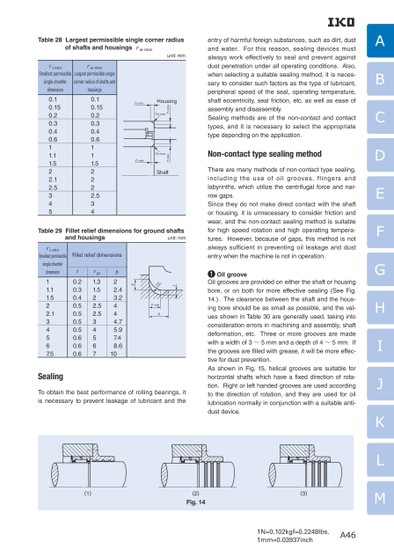
1N=0.102kgf=0.2248lbs.1mm=0.03937inchABCDEFGHIJKLMTable 28 Largest permissible single corner radius entry of harmful foreign substances, such as dirt, dust and water. For this reason, sealing devices must always work effectively to seal and prevent against dust penetration under all operating conditions. Also, when selecting a suitable sealing method, it is neces-sary to consider such factors as the type of lubricant, peripheral speed of the seal, operating temperature, shaft eccentricity, seal friction, etc. as well as ease of assembly and disassembly.Sealing methods are of the non-contact and contact types, and it is necessary to select the appropriate type depending on the application.Non-contact type sealing methodThere are many methods of non-contact type sealing, including the use of oil grooves, flingers and labyrinths, which utilize the centrifugal force and nar-row gaps.Since they do not make direct contact with the shaft or housing, it is unnecessary to consider friction and wear, and the non-contact sealing method is suitable of shafts and housings ras maxunit: mm rs minSmallest permissible ras maxLargest permissible single single chamfer corner radius of shafts and dimensionhousingsHousingrs minras maxrs minrs minras maxShaftrs min0.10.150.20.30.40.65111..52222340.10.150.20.30.40.6111.1.5.1222.5345Table 29 Fillet relief dimensions for ground shafts for high speed rotation and high operating tempera-tures. However, because of gaps, this method is not always sufficient in preventing oil leakage and dust entry when the machine is not in operation.1 Oil grooveOil grooves are provided on either the shaft or housing bore, or on both for more effective sealing (See Fig. 14.). The clearance between the shaft and the hous-ing bore should be as small as possible, and the val-ues shown in Table 30 are generally used, taking into consideration errors in machining and assembly, shaft deformation, etc. Three or more grooves are made with a width of 3〜5 mm and a depth of 4〜5 mm. If the grooves are lled with grease, it will be more effec-tive for dust prevention.As shown in Fig. 15, helical grooves are suitable for horizontal shafts which have a xed direction of rota-tion. Right or left handed grooves are used according to the direction of rotation, and they are used for oil lubrication normally in conjunction with a suitable anti-dust device.and housings unit: mm hsgrtrs minbFillet relief dimensionsb 2 2.4 3.2 4 4 4.7 5.9 7.4 8.610rgs1.31.5.5222.534567t 0.20.30.40.50.50.50.50.60.60.6rs minSmallest permissible single chamfer dimension111.1.5.12234567.5SealingTo obtain the best performance of rolling bearings, it is necessary to prevent leakage of lubricant and the (1)(2)Fig. 14(3)A46
 | <
| <  |
|  > |
> |  >>
>>