>> P.39
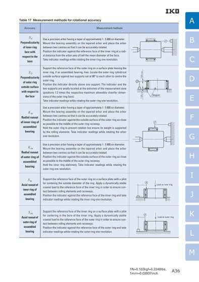
1N=0.102kgf=0.2248lbs.1mm=0.03937inchABCDEFGHIJKLMStopper1.2rs max1.2rs maxLoad on inner ringLoad on outer ringA36Table 17 Measurement methods for rotational accuracyAccuracySdPerpendicularity of inner ring face with respect to the boreSDPerpendicularity of outer ring outside surface with respect to Measurement methodsUse a precision arbor having a taper of approximately 1 : 5 000 on diameter.Mount the bearing assembly on the tapered arbor and place the arbor between two centres so that it can be accurately rotated.Position the indicator against the reference face of the inner ring at a radi-al distance from the arbor axis of half the mean diameter of the face.Take indicator readings while rotating the inner ring one revolution.Support the reference face of the outer ring on a surface plate leaving the inner ring, if an assembled bearing, free. Locate the outer ring cylindrical outside surface against two supports set at 90° to each other to centre the outer ring.Position the indicator directly above one support. The indicator and the two supports are axially located at the extremes of the measurement zone (positions 1.2 times the respective maximum allowable chamfer dimen-the facesions of the outer ring face).Take indicator readings while rotating the outer ring one revolution.KiaRadial runout of inner ring of assembled bearingUse a precision arbor having a taper of approximately 1 : 5 000 on diameter.Mount the bearing assembly on the tapered arbor and place the arbor between two centres so that it can be accurately rotated.Position the indicator against the outside surface of the outer ring as close as possible to the middle of the outer ring raceway.Hold the outer ring to prevent rotation but ensure its weight is supported by the rolling elements. Take indicator readings while rotating the arbor one revolution.KeaRadial runout of outer ring of assembled bearingUse a precision arbor having a taper of approximately 1 : 5 000 on diameter.Mount the bearing assembly on the tapered arbor and place the arbor between two centres so that it can be accurately rotated.Position the indicator against the outside surface of the outer ring as close as possible to the middle of the outer ring raceway.Hold the inner ring stationary. Take indicator readings while rotating the outer ring one revolution.SiaAxial runout of inner ring of assembled bearingSeaAxial runout of outer ring of assembled bearingSupport the reference face of the outer ring on a surface plate with a pilot for centering the outside diameter of the ring. Apply a dynamically stable coaxial load to the reference face of the inner ring in order to ensure con-tact between rolling elements and raceways.Position the indicator against the reference face of the inner ring and take indicator readings while rotating the inner ring one revolution.Support the reference face of the inner ring on a surface plate with a pilot for centering in the bore of the inner ring. Apply a dynamically stable coaxial load to the reference face of the outer ring in order to ensure con-tact between rolling elements and raceways.Position the indicator against the reference face of the outer ring and take indicator readings while rotating the outer ring one revolution.
 | <
| <  |
|  > |
> |  >>
>>