>> P.88
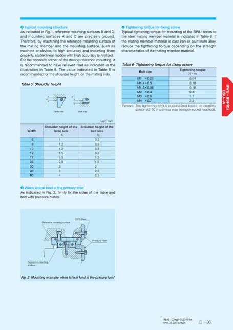
Ⅱ-80❹TighteningtorqueforfixingscrewTypicaltighteningtorqueformountingoftheBWUseriestothesteelmatingmembermaterialisindicatedinTable6.Ifthematingmembermaterialiscastironoraluminumalloy,reducethetighteningtorquedependingonthestrengthcharacteristicsofthematingmembermaterial.Table6TighteningtorqueforfixingscrewBoltsizeM1×0.25M1.4×0.3M1.6×0.35M2×0.4M3×0.5M4×0.7TighteningtorqueN・m0.040.100.150.311.12.5Remark:ThetighteningtorqueiscalculatedbasedonpropertydivisionA2-70ofstainlesssteelhexagonsocketheadbolt.❷TypicalmountingstructureAsindicatedinFig.1,referencemountingsurfacesBandD,andmountingsurfacesAandCarepreciselyground.Therefore,bymachiningthereferencemountingsurfaceofthematingmemberandthemountingsurface,suchasmachineordevice,tohighaccuracyandmountingthemproperly,stablelinearmotionwithhighaccuracyisrealized.Fortheoppositecornerofthematingreferencemounting,itisrecommendedtohaverelievedfilletasindicatedintheillustrationinTable5.ThevalueindicatedinTable5isrecommendedfortheshoulderheightonthematingside.Table5ShoulderheightShoulderheightoftheShoulderheightoftheWidthtablesidebedsideunit:mmTablesideBedsideh2h16810121725304060h111.21.21.52.52.5334h20.50.80.80.81.21.522.52.5❸WhenlateralloadistheprimaryloadAsindicatedinFig.2,firmlyfixthesidesofthetableandbedwithpressureplates.ReferencemountingsurfaceMarkPressurePlateReferencemountingsurface2.giFMountingexamplewhenlateralloadistheprimaryload
 | <
| <  |
|  > |
> |  >>
>>