>> P.197
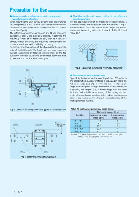
PrecautionforUse❶Mountingsurface,referencemountingsurfaceand❷ShoulderheightandcornerradiusofthereferencetypicalmountingstructuremountingsurfaceFortheoppositecornerofthematingreferencemounting,itisrecommendedtohaverelievedfilletasindicatedinFig.5.RecommendedvaluefortheshoulderheightandcornerradiusonthematingsideisindicatedinTable17.1andTable17.2.WhenmountingtheLWFseries,properlyalignthereferencemountingsurfaceBandDofthetrackrailandslideunitwiththereferencemountingsurfaceofthetableandbedandfixthem.(SeeFig.3.)ThereferencemountingsurfacesBandDandmountingsurfacesAandCarepreciselyground.Machiningthemountingsurfaceofthetableandbed,suchasmachineordevice,tohighaccuracyandmountingthemproperlywillensurestablelinearmotionwithhighaccuracy.Referencemountingsurfaceoftheslideunitistheoppositemark.Thetrackrailreferencemountingsideofthesurfaceisidentifiedbylocatingthemarkonthetopsurfaceofthetrackrail.Itisthesidesurfaceabovethemark(inthedirectionofthearrow).(SeeFig.4)5.giFCornerofthematingreferencemounting❸TighteningtorqueforfixingscrewTypicaltighteningtorqueformountingoftheLWFseriestothesteelmatingmembermaterialisindicatedinTable16.Whenvibrationandshockofthemachineordevicearelarge,fluctuatingloadislarge,ormomentloadisapplied,fixitbyusingthetorque1.2to1.5timeslargerthanthevalueindicatedinthetableasnecessary.Ifthematingmembermaterialiscastironoraluminumalloy,reducethetighteningtorquedependingonthestrengthcharacteristicsofthematingmembermaterial.Table16TighteningtorqueforfixingscrewBoltsize4×0.75×0.86×18×1.25MMMMM10×1.5TighteningtorqueN・mHighcarbonsteel-Stainlesssteel-madescrewmadescrew4.18.013.632.763.92.55.08.5--Remark:Thetighteningtorqueiscalculatedbasedonstrengthdivision12.9andpropertydivisionA2-70.DCAB3.giFReferencemountingsurfaceandtypicalmountingstructureTrackrailSlideunitReferencemountingsurfaceDBMarkMark4.giFReferencemountingsurfaceⅡ-147
 | <
| <  |
|  > |
> |  >>
>>